Introduction: From Cathedrals to Code
Architecture has always advanced when tools changed the rules. Medieval masons stretched stone to its limits with flying buttresses; the Industrial Revolution standardized parts; the digital turn unlocked free-form geometry. Today, robotic arms in 3D concrete printing mark the next inflection point. Precision mechatronics, smart materials, and algorithmic design are converging to push construction beyond the constraints of formwork and manual labor. What once required weeks of carpentry and curing can now be shaped directly from data layer by layer by an articulated arm that moves with the calm certainty of code.
This is not a simple swap of trowel for robot. It’s a system change: from drawing to toolpath, from batch casting to continuous deposition, from approximate tolerances to millimetric control. The result is new architectural language lighter, faster, more sustainable and a production logic that finally treats construction like advanced manufacturing.
Design Logic: Why Articulated Arms Change the Game
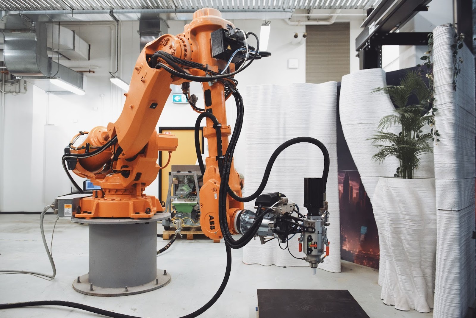
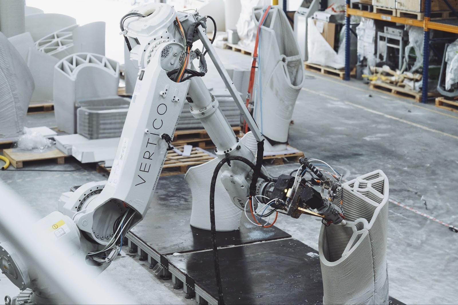
Robots first conquered automotive lines because reach, repeatability, and stiffness could be engineered into a six-axis arm. Those same qualities are transformational in 3D concrete printing:
- Degrees of freedom. A typical industrial arm provides 6–7 axes, enabling complex tool orientations. Instead of printing only vertical, the nozzle can tilt, weave, or bridge, improving interlayer adhesion and enabling overhangs that would defeat a simple gantry.
- Reach versus footprint. Arms deliver large effective work envelopes without the site-wide rails or frames of gantries. On cramped sites or for retrofit applications, this compactness is decisive.
- End-effector flexibility. Swapping a nozzle for a finishing trowel, fiber feeder, or inspection camera takes minutes. A single robot can print, compact, trim, and inspect.
- Closed-loop precision. Joint encoders, torque sensing, and vision allow the arm to adapt on the fly correcting for thermal expansion, pump pressure fluctuations, or substrate irregularities.
Under the hood, this is a marriage of kinematics and material science. The robot’s trajectories are not arbitrary; they are tuned to the rheology of a thixotropic cementitious mix that must flow, hold, and gain strength in a rhythm measured in seconds.

The Materials: Rheology as a Design Constraint
Concrete for additive manufacturing in construction is fundamentally different from conventional mixes. Without formwork, material behavior is the mold.
- Pumpability & extrudability. Particle packing, water-to-binder ratio, and admixtures (superplasticizers, viscosity modifiers) are tuned to maintain laminar flow through hoses and nozzle.
- Buildability. Once deposited, the filament must support subsequent layers. Thixotropy and early-age stiffness are manipulated with accelerators or inline activators near the nozzle.
- Interlayer bonding. Cold-joint risk is mitigated by time-controlled layer intervals, mechanical weaving, or surface activation (e.g., micro-rilling). A robotic arm can modulate speed and nozzle angle to “iron” layers together.
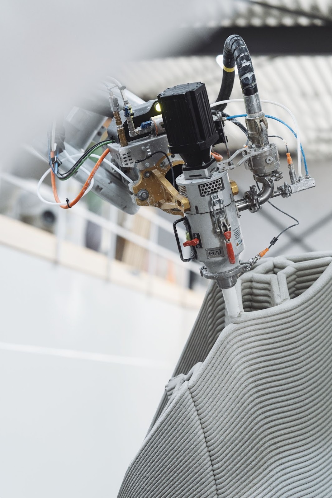
Here, nozzle design is as architectural as it is mechanical: oval or multi-slot tips lay flatter beads for thin walls or ribbed profiles for structural ribs; integrated air knives improve edge definition; coaxial nozzles enable fiber or cable co-extrusion for reinforcement.
Toolpaths: From Parametric Geometry to Robotic Motion
Parametric modeling connects design intent to machine action. The pipeline:
- Geometry conditioning. Surfaces become offset shells, lattices, or rib-and-skin systems optimized for printability and structural performance.
- Print path planning. Slicing is no longer strictly planar; with robotic arms, we can adopt non-planar, conformal, or variable-thickness paths that align filaments with principal stress directions.
- Kinematic feasibility. Inverse kinematics checks joint limits and singularities. If a pose is unreachable, the algorithm perturbs the path or adjusts nozzle orientation.
- Process simulation. Digital twins simulate deposition, thermal/moisture gradients, and curing kinetics to predict sag, bulge, or collision.
- Code generation & synchronization. The printer controller orchestrates pump pressure, valve timing, and robot speed. Acceleration/jerk limits are tuned so corners stay crisp and filaments don’t neck.
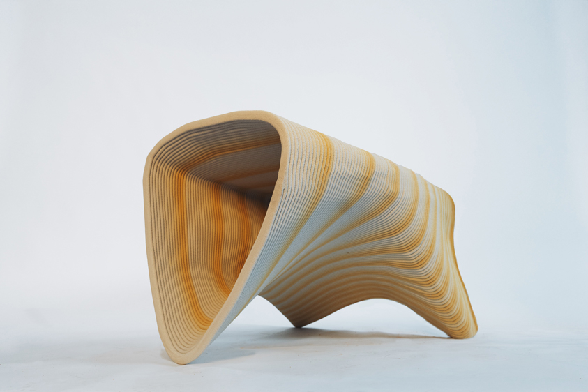
When the robot can tilt and weave, we gain new micro-architectures like sinusoidal infill or anisotropic bead patterns that stiffen walls without adding mass. Think Roman pozzolana wisdom, now expressed as computational craft.
Reinforcement: Beyond Rebar-in-a-Mold
Formworkless printing forces us to rethink reinforcement:
- Post-tensioned ducts printed into walls can be threaded with tendons after curing, enabling slender spans.
- Co-printing fibers (basalt, AR-glass, steel microfibers) elevates tensile capacity and crack control without cage assembly.
- Cable or bar co-extrusion via secondary feeds lays continuous reinforcement along stress lines.
- Hybrid strategies combine printed stay-in-place formwork with minimal rebar cages or shotcrete skins, exploiting each material’s strengths.
Robotic arms shine here: the same manipulator that prints can pick-and-place inserts, anchors, or conduits mid-build with sub-millimeter consistency.
Quality and Sensing: Toward Self-Verifying Construction
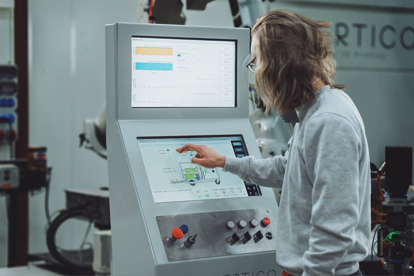
Traditional QC relies on samples; printed construction benefits from in-situ monitoring:
- Vision & LiDAR check bead width, layer height, and geometry against the digital twin in real time.
- Acoustic/ultrasonic sensors estimate early-age stiffness and detect voids.
- Load cells & pressure sensors close the loop between pump and nozzle, stabilizing flow despite temperature or material batch variation.
- Environmental sensing (humidity, wind, temperature) adapts print speed or accelerator dose on the fly.
With this data, the robot becomes a self-auditing craftsperson. Deviations trigger automatic path correction or localized rework passes. Every layer is logged, building a traceable quality record that accelerates approvals and critically paves the way to updated codes.
Why Robotic Arms, Not Just Gantries?
Gantry systems are excellent for large, repeatable footprints. But robotic arms in 3D concrete printing deliver advantages that are architectural and operational:
- Freedom of orientation. Non-planar bead placement reduces stair-stepping and improves structural continuity around openings and curves.
- Complex interior finishes. Arms can articulate inside shells to print integrated ribbing, service chases, or acoustic textures.
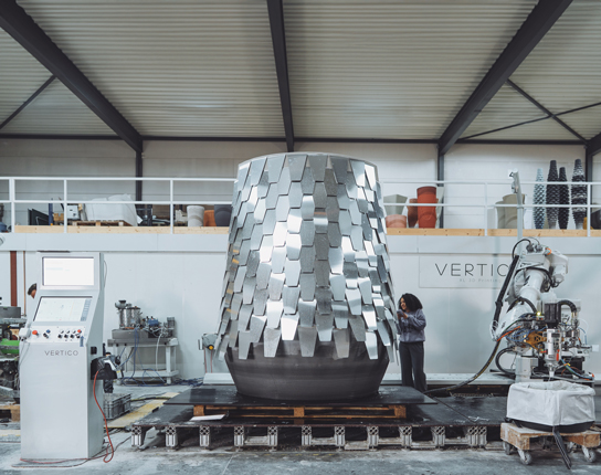
- Multi-tool workflows. One robot prints, the next mills or grinds, a third inspects an orchestrated cell like aerospace manufacturing.
- Site agility. Arms ride on mobile bases or overhead rails, hopping between zones without re-rigging a massive frame.
The economic story is equally compelling: fewer bespoke molds, shorter takt times, and higher utilization from multi-role robots. In the right scope, this is CapEx that behaves like a platform, not a product.
Sustainability: Material Efficiency as First Principle
Sustainability isn’t a footnote, it's the design brief.
- Formwork elimination cuts timber, plywood, and disposable plastics from the waste stream.
- Geometry-driven optimization (voided cores, ribbed shells, lattice infill) reduces cement usage while maintaining stiffness less mass, same performance.
- Local materials (supplementary cementitious materials, recycled aggregates) lower embodied carbon; printable mixes increasingly incorporate slag, fly ash replacements, calcined clays, or limestone fillers.
- Operational efficiency. Precise deposition shrinks rework; digital QA reduces over-design margins baked in “just in case.”
- Design for deconstruction. Printed modules with integrated connectors support circular strategies print, use, reclaim.
Considering concrete’s global footprint, even single-digit percentage savings at scale are climate-relevant. Robotic control is how we get there reliably.
Practical Benefits for Architects and Builders
Speed without surprise. Once the print file is validated, cycle times become predictable. Walls or bespoke elements can be produced overnight with minimal supervision.
Design freedom that’s buildable. Filleted transitions, variable thicknesses, double-curved surfaces the shapes designers love often die in formwork. Printing makes them routine, and parametric rulesets keep costs in check.
Lean logistics. No bulky molds, fewer deliveries, smaller crews. The site footprint shrinks and safety improves fewer working-at-height tasks, less heavy formwork handling.
Integrated services & finishes. Print conduits, niches, and surface textures in a single pass. Add robotic finishing for Class A surfaces where required.
Repeatable customization. Change a radius or opening size in code, not carpentry. Mass customization finally behaves like mass production.
Cost savings that scale. Eliminating bespoke formwork, optimizing material usage, and reducing rework cut direct costs; shorter schedules shrink prelims and site overhead; smaller teams lower labor spend delivering measurable savings from prototype to series production.
Implementation Playbook: From Pilot to Production
- Identify the right use cases. Start with non-load-bearing elements, street furniture, site walls, or cores with hybrid reinforcement. Build organizational confidence before tackling fully structural shells.
- Assemble a flexible cell. A 6-axis arm (10–20 kg payload) with pump, mixer, and heated hoses covers most small-to-mid elements; heavier arms address larger sections. Plan for quick-change end-effectors.
- Codify printability rules. Minimum radii, overhang limits, bead widths, layer heights turn them into parametric constraints so architects design within the machine’s sweet spot.
- Establish the digital thread. BIM ↔ slicer ↔ robot controller ↔ QA database. Treat every part as data-rich, from mix batch to final scan.
- Train the team. Cross-train architects, structural engineers, and operators. The biggest gains come when design and production speak the same language.
- Engage early with approvals. Share test data, mock-ups, and monitoring protocols with inspectors. Transparency accelerates acceptance.
Case Patterns: What the Arm Enables
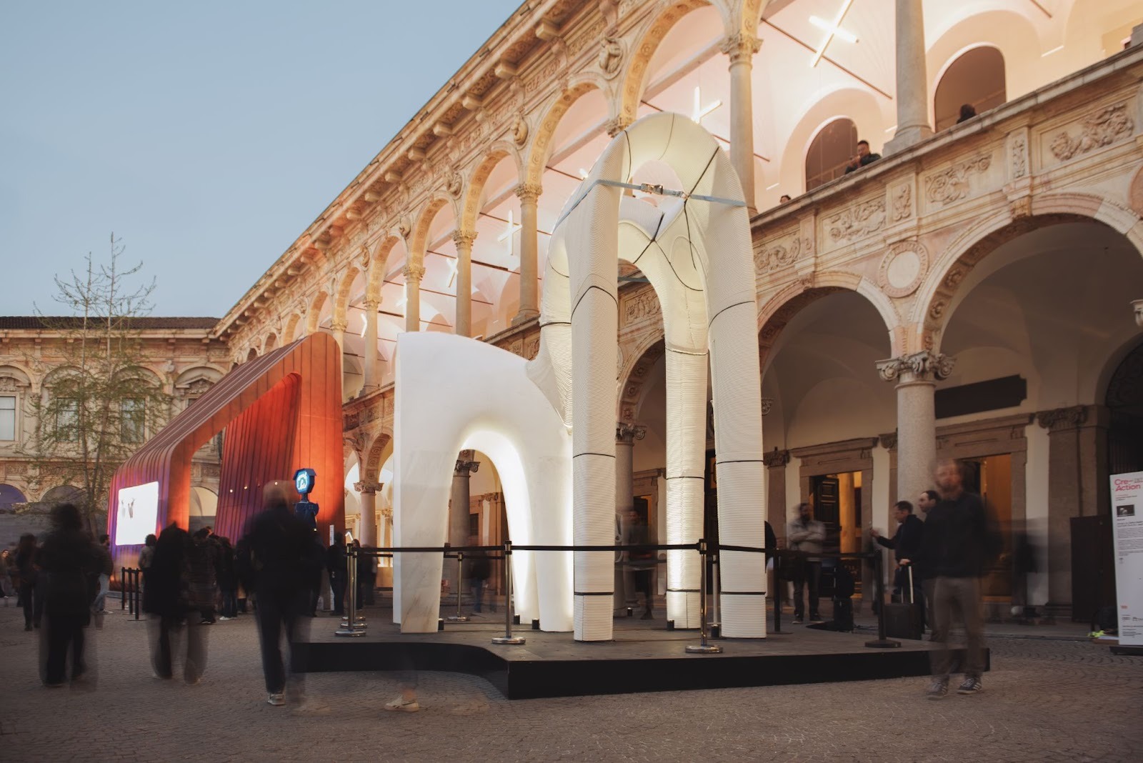
- Vaulted light shells. Non-planar toolpaths align filaments with compression thrust lines, enabling thin, post-tensioned vaults with minimal material.
- Porous acoustic walls. Variable bead spacing and amplitude create tuned cavities for sound diffusion function embedded in geometry.
- Infrastructure retrofits. Arms mounted on mobile platforms print stay-in-place forms for bridge repairs, then backfill with high-performance grout.
- Facade customization. Repetitive panels share a base script; site-specific motifs are parameter tweaks, not new molds.
Each pattern blends structural logic with expressive form technology serving architecture, not the other way around.
Standards, Safety, and the Path to Scale
Codes are catching up. In the interim, performance-based design and rigorous testing build the bridge. Safety remains paramount: safeguarded cells, emergency stops, verified toolpaths, and clear exclusion zones. As the ecosystem matures materials suppliers, slicer software, certification bodies the friction drops. Expect:
- Multi-material printing (cementitious + insulation + waterproof skins) in a single robotic choreography.
- AI-driven deposition that adapts bead strategy to live sensor feedback, optimizing for carbon, cost, or speed on demand.
- On-site swarms. Several smaller arms cooperating one prints, one finishes, one inspects shrinking overall takt time.
- Wider code recognition as datasets prove consistency and long-term durability (freeze-thaw, fire, and carbonation resistance).
Conclusion: Craft, Reimagined as Code
Robotic arms don’t replace craftsmanship; they reframe it. The craft moves upstream into mix design, toolpath logic, and real-time control while the robot executes with tireless precision. For architects and engineers, the reward is profound: structures that are lighter, lower-carbon, and formally liberated, delivered with the reliability of modern manufacturing. The cathedral builders would recognize the ambition. They might even nod at the elegance of a bead that carries force the way a stone rib once did.
How robotic arms are revolutionizing 3D concrete printing isn’t a slogan. It’s a blueprint for the next era of construction where sustainability is engineered, not just promised, and where design freedom translates directly into built reality.

%20(1).jpg)
%20(1)%20(1)%20(1)%20(1).jpg)
.jpg)
%20(2).jpg)
%20(2)%20(2).jpg)

.jpg)
.jpg)